
2002 – Unbuilt Dublin – DDDA Pedestrian Bridge

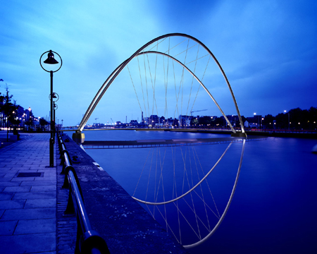
Symbolically the new bridge is seen as an elegant gateway linking the old city of business and power to the new city of international finance and information technology. High leaning arches, spanning 80 metres, delicately balance a gently curved steel deck suspended by finely threaded steel ropes. The structure of the bridge and it¹s mechanical requirements are inspired by recent developments in tilted arch bridges and by the methods of bascule bridge design, such as the Œbucket¹ bridge nearby which used water as a counterweight.
The bridge comprises two elements. Two cantilever sections from each quay and an opening section at the centre 40 metres in length. The opening section of the deck is suspended from the arches by 26 mm diameter steel ropes which are threaded through sheaves concealed within the arches. The cantilevered sections and the arches, which have an elliptical steel section (1200 x 700 mm at the base tapering to 700 x 900 at the crown, with a wall thickness of 20 mm), are all supported from two piled concrete piers in the river located 10 metres equidistant from each quay wall, providing an economic and effective structure.
The opening section of the deck has slung beneath it four 600 mm diameter cylindrical insulated tanks carrying 17000 litres of water. These are full when the deck is down and then as the deck rises the water is released appearing like a waterfall beneath the arches. To raise the deck the arches move apart and the steel ropes pull the deck upwards to leave room for ships to pass beneath.
The weight of the arches is balanced by the weight of the deck and water. Releasing the water lightens the deck and allows the arches to spread and the deck to rise. The movement of the arches is critical and needs to be symmetrical. Therefore, the lifting mechanism will be geared and fail safe and will be controlled by synchronised motors located in the abutments linked to the pivot on which the arches rotate. A small control booth is located on the north quay from which the mechanism can be activated.
The release of the water is activated by a mechanical rotating arm which turns the four tanks simultaneously and in a controlled manner away from each other and towards the river west and east of the bridge. The rotation causes a sheet of water to spill out over the edge of the tank until it has completed its 180 deg. rotation and the opening slit is now facing downward toward the river. To close the bridge, the tanks are rotated through a further 180 deg until the opening slit is again upright and under the deck. Filtered water from the river is now pumped into the 4 tanks simultaneously. As this occurs the deck moves downward to the closed position.
One imagines that the opening of the bridge will be a public event or spectacle – people may want to stand and watch the water falling to the river and the movement of the arches.
When the bridge is in the open position the air draught is 23.5 metres at Mean Low Water Mark Spring Tide, and 20.5 metres at Mean Low Water Mark Neap Tide. When the bridge is closed the distance between the soffit level of the deck and the water is 6.5 metres at Mean Low Water Mark Spring Tide and 3.5 metres at Mean Low Water Mark Neap Tide. At worst condition ( Mean High Water Mark Spring Tide) the distance is 1.6 metres approx.
The deck is gently curved and is directly and easily accessible from the quayside and the access is the same for everyone. Proposals for the development of the campshire surrounding the bridge landing points are included in the plans. It is assumed that there will be pedestrian crossings at these points. Accessing the bridge in an easy and relaxed manner is crucial to the success of the bridge as a civic amenity. It should be as simple as turning a corner and walking down a street. The deck itself is finished in oak on an aggregate base. The hand rail is a generous, shaped, oak rail which also encourages leaning for viewing. The balustrade is painted steel.
The bridge deck is lit via vertical fluorescent tubes located at 1.5m centres in the balustrade upstands. The fittings are set back within the upstands and are protected at the front by a stainless steel mesh stretched across the two upstand uprights. These throw horizontal bands of light across the deck.
Floodlights mounted on the piers are directed upwards along the arches. The steel ropes are illuminated by smaller floodlights mounted on the edge of the deck outside the handrails. The flood lights pick out the structure but in addition provide spill lighting to supplement the deck lighting.
Share!
Cite This Article
Published March 2, 2010 | Last Updated October 24, 2015